To achieve energy security and the "dual carbon" goals, charging piles require the support of smart grids, possessing scalability and upgradability. They can be compatible with various energy storage systems and can integrate clean energy sources such as photovoltaic, wind power, and hydrogen. Additionally, it is essential to plan for V2G (Vehicle-to-Grid) coordination with the grid side, enhancing service capabilities for users while also cooperating with grid development, reducing pressure on the grid, and improving grid interaction. This includes orderly charging, vehicle-grid collaboration, aggregated green electricity, and a comprehensive carbon management system throughout the entire lifecycle.
Ev charging stations AC, commonly known as "slow charging piles," are fixedly installed outside electric vehicles and connected to the AC power grid. They adhere to national standards using 220V single-phase AC power, serving as power supply devices that provide AC power to the electric vehicle's onboard charger (a charger permanently installed on the electric vehicle). AC charging piles only output power without charging functionality; they require connection to the vehicle's onboard charger for charging, acting as a power control unit. Utilizing AC charging mode compliant with national standards, their maximum output power is 7kW, typically requiring 5-8 hours to fully charge a vehicle's battery from empty.
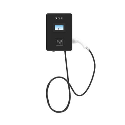
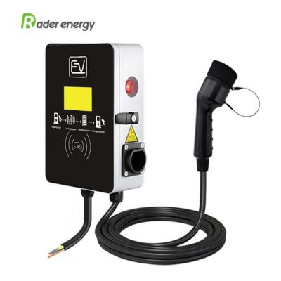
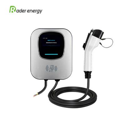
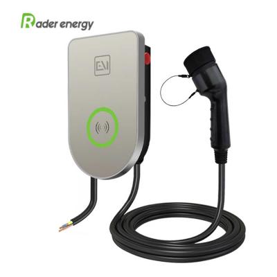
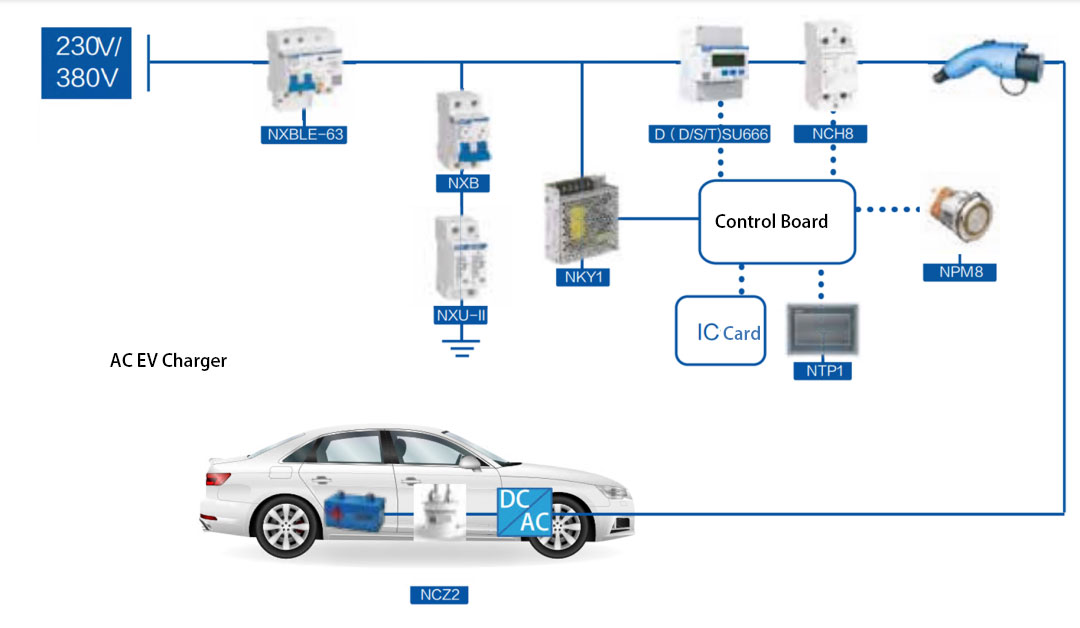
The main structure of charging piles comprises the pile body, charging control module, display module, communication module, connecting cables, safety protection devices, and other components.
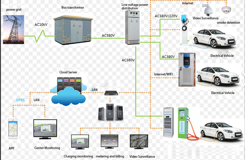
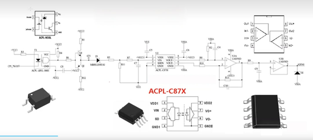
 System topology diagram
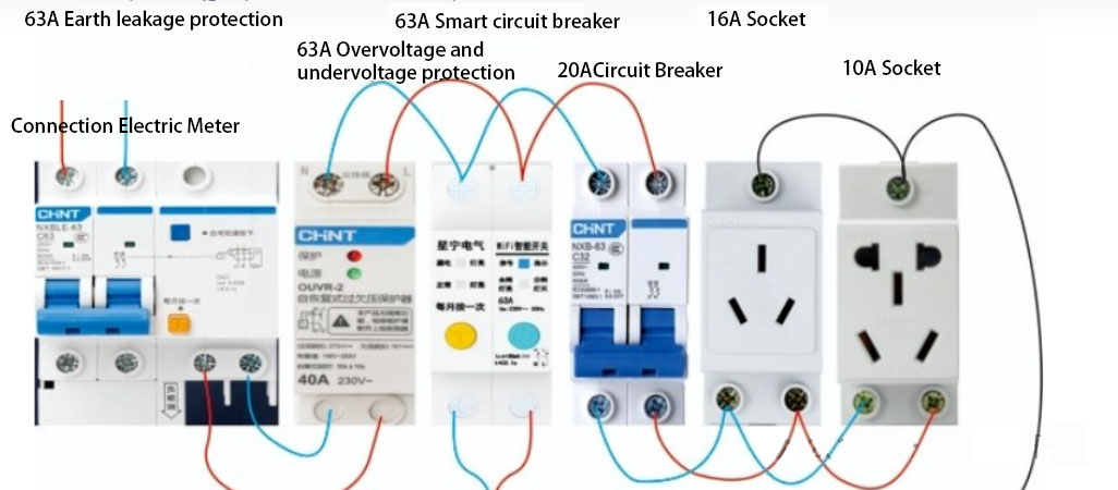
Residual current detection and protection are essential functional modules for every charging pile's mainboard, directly related to user safety and mitigating fire risks caused by persistent ground fault currents. Currently, four primary types of residual current detection and protection modules (RCDs) exist: Type A, Type B, Type F, and Type AC, differentiated by their ability to detect different types of fault currents.
Due to varying international standards, Type B RCDs are commonly used on foreign charging pile mainboards. With broader current detection capabilities, Type B RCDs can detect a wider range of fault currents, including sinusoidal AC residual currents and smooth DC residual currents. This comprehensive current detection capability enables Type B RCDs to more effectively protect charging pile circuits from various electrical faults, thereby reducing the risk of fires and personal safety accidents. In China, Type A and Type AC RCDs are prevalent. With the implementation of the new national standard GB/T 18487.1-2023, the charging pile market's demand for safety and reliability is growing, and charging pile mainboards equipped with Type B RCDs will have a more competitive edge.
Features supported include emergency stop charging, NFC card swiping, clock display, electricity calculation, 4G data transmission, historical log inquiry, indicator light display, voice reminders, and screen display.
Overview of AC Charging Principles:
Introduction to Functional Parameters
Function Description
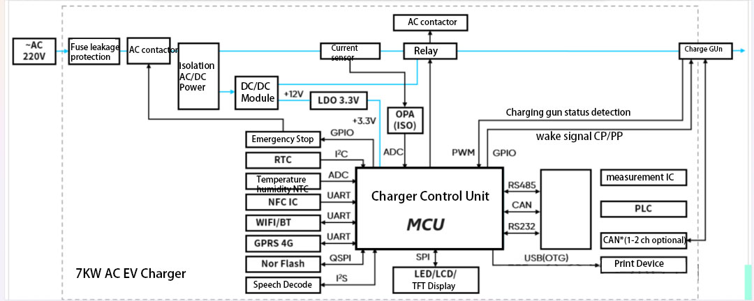
(1) Microprocessor Module
The microprocessor module, being one of the core components of the AC charging pile's mainboard, processes commands from users and controls the operation of the AC charging pile accordingly. This module comprises a central processing unit (CPU), memory, a clock, and other necessary integrated circuits.
(2) Communication Module
The AC charging pile needs to communicate with the back-end server and mobile devices. The communication module provides various interfaces, such as Ethernet, RS485, and community networks. It is equipped with built-in NFC chips/BLE/WIFI modules, primarily responsible for transmitting the charging pile's data to the back-end server or mobile devices to enable remote monitoring and management. It can also communicate with electric vehicles via CAN communication or through CP/PP signals for interaction.
(3) Charging Control Module
The charging control module connects with other electronic components on the AC charging pile's mainboard to control the entire charging process. It identifies vehicle models, confirms charging requirements, determines suitable charging methods and power, and monitors various parameters during charging, including charging current and voltage.
(3) Power Module
Power is one of the indispensable and crucial factors for all systems to operate, whether it's related system operations or charging requirements for charging stations. The power module's primary function is to provide the charging station with a corresponding DC power supply.
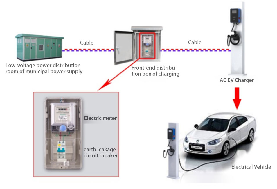
(4) Design of the Electric Energy Metering Module
The electric energy meter is also an essential component during the design of an AC electric vehicle charging station system. Its actual function is to measure the actual consumption in the circuit. Its performance parameters fully comply with the national standard GB/T17215.321-2008. Due to the use of high-precision measurement chips and high-speed MCU data processing units, the meter can accurately measure electrical parameters such as power, voltage, and current during practical applications. It boasts high stability and has the advantage of automatically saving data during power outages. Additionally, since the meter requires RS-485 communication, while the mainboard uses TTL communication, it is necessary to integrate these two incompatible modules to enable normal communication between the mainboard and the meter.
(5) Sensor Module
The sensor module collects various data from the environment where the AC charging station's mainboard is located, such as temperature, humidity, and flammable gas concentration. These data can be used to optimize the usage efficiency of the AC charging station and ensure the safety, reliability, and efficiency of the entire charging process.
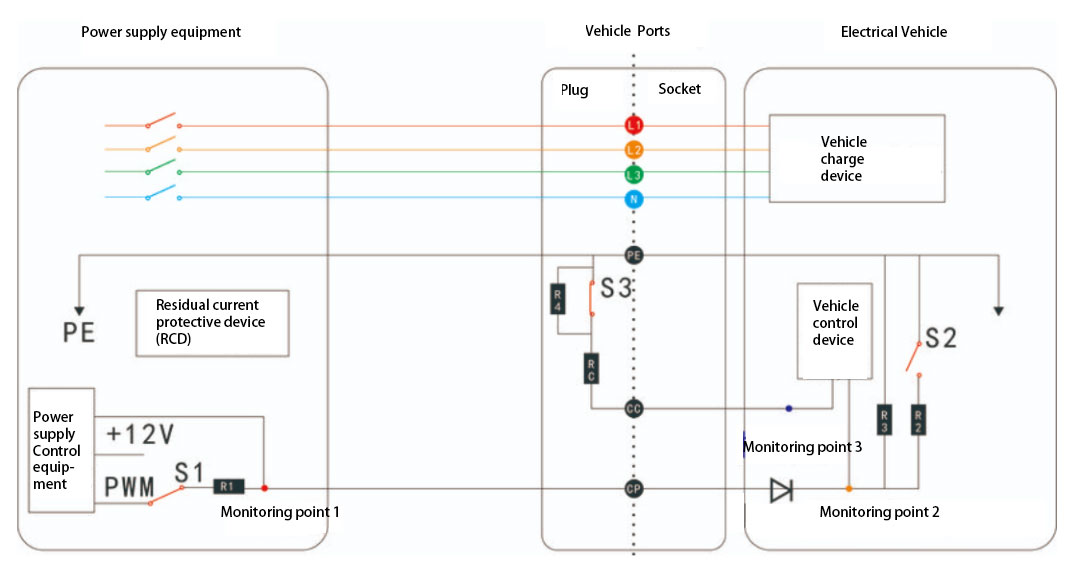
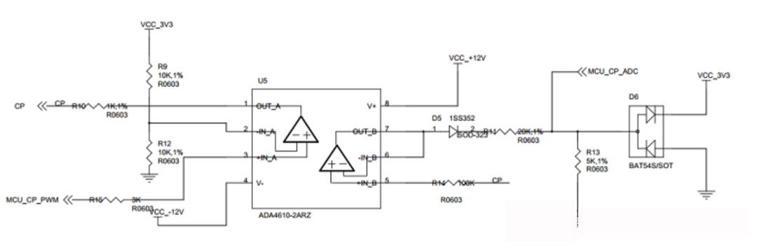
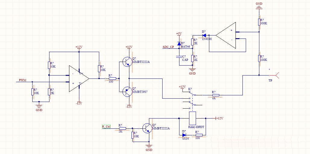
(6) Control and Guidance Module
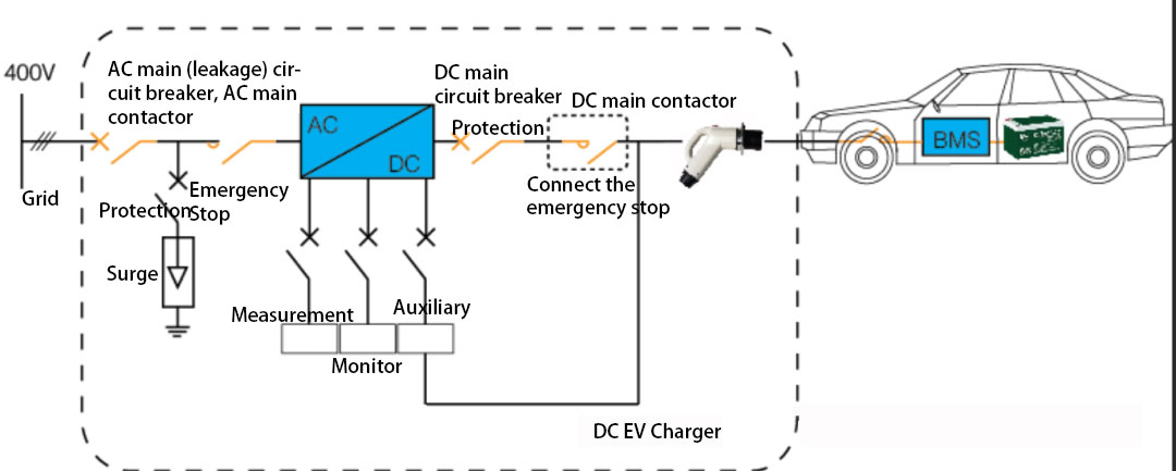
The driver circuit and on-board BMS system are also crucial aspects of the charging station design. During this system's design, CC and CP can fulfill the corresponding connection requirements, and relevant charging parameters can be effectively confirmed during connection to meet actual charging needs. Currently, the PWM signals specified in national standards are generally provided by power control devices. This circuit can output bipolar PWM during actual operation and also achieve +12V voltage output during operation, satisfying electric vehicles' actual voltage usage requirements.
(7) Safety Protection Module
In the AC charging station's mainboard, the safety protection module ensures the safety and reliability of the charging process. It can detect data such as battery capacity, voltage, and temperature during charging and ensures the safety of vehicles and users through system control. It provides protection against overcurrent, short circuit, overvoltage, undervoltage, electric leakage, lightning strikes, charging, and online interruption. Board-mounted isolation devices, fuses, and leakage protectors safeguard device safety and system stability.
Charging Timing Waveforms
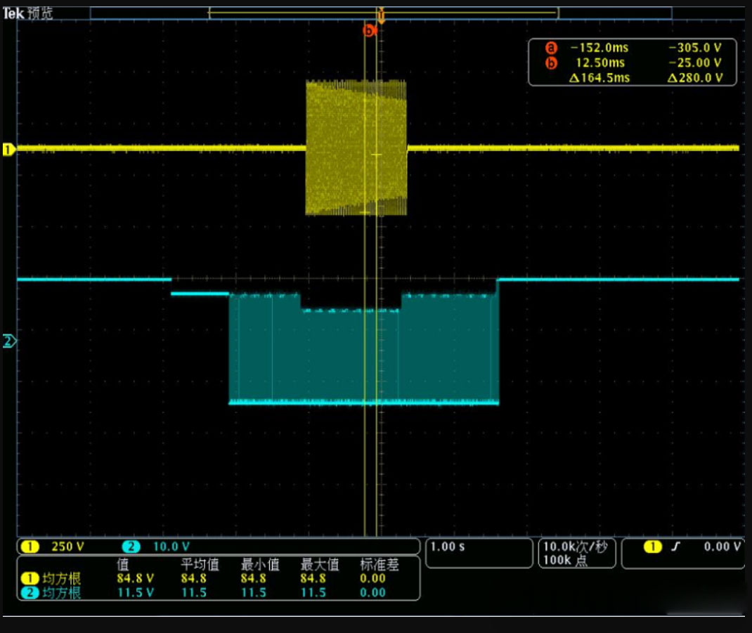
(1) Simulate the insertion of the charging gun, and the CP voltage changes from 12V to 9V.
(2) Send the command to start charging, and the charging station begins to send PWM, with the waveform changing from 9V constant to 9V PWM.
(3) Simulate the closure of the S2 switch in the electric vehicle, and the CP changes from 9V PWM to 6V PWM.
(4) Simulate the completion of charging, and the S2 switch is disconnected, with the CP changing from 6V PWM to 9V PWM.
(5) Simulate the removal of the charging gun, and the CP changes from 9V PWM to 12V PWM.
(6) 12V PWM changes to 12V.
Closed-Loop Timing
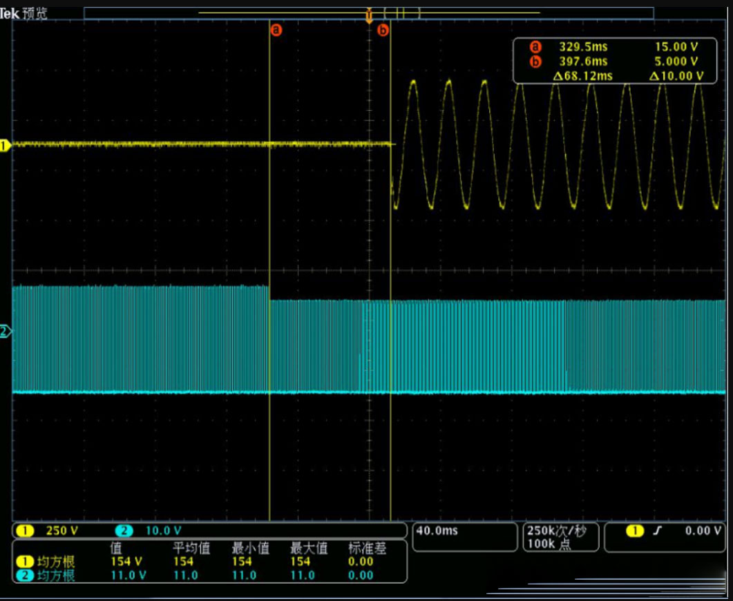
As shown in the diagram above, after the CP switches from state 2' to state 3', it takes approximately 68 ms to close the AC loop, thus meeting the timing requirements.
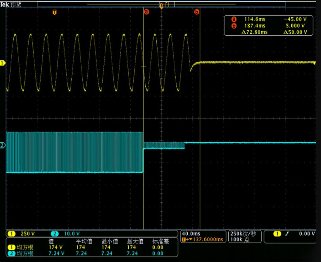
During charging, when the CP is grounded, the charging station disconnects the AC output within 100 ms, also meeting the timing requirements.
Choosing between single-phase and three-phase po
"Revolutionizing energy storage, advancements in
Here is an introduction to one of the best batte
Contact: Thomas
Phone: +8618025306280
Tel: +86-0755-32872175
Email: hello@raderenergy.com
Add: Block A, Ketujia Building, Fucheng Street, Longhua District, Shenzhen, PRC
 English